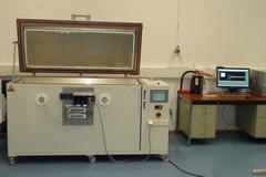
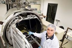
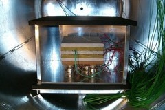
Temperature cycles, pressure and TQCM data are logged with a data acquisition system. Flight hardware or sensitive samples can be put into the chamber through a class 5 laminar flow box. If necessary, we can design and manufacture suitable specimen mounting devices which are compatible with our heating and cooling modules.
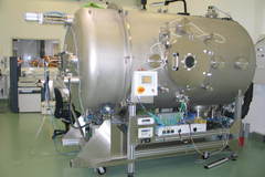
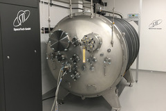
The vacuum chamber is provided with a cryo-pump, which means that the system is oil free. The cold trap is installed between shroud and cryo-pump.
The vacuum chamber can be operated and monitored remotely. It is provided with a safety over-temperature shutdown system to protect the samples. Both the controls and vacuum pumps are protected by a UPS unit which allows a controlled shutdown in the event of power failure and notifies DLR staff via several mobile communication channels.
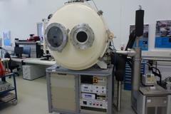
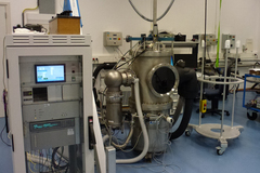
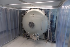
The Space Simulation Chamber (SSC) of the Institute of Optical Sensor Systems can be equipped for optical test by outside illumination stimulation as well. Therefor an optical window made from fused silica will be mounted to chamber bumped boiler head. A colimator or an integrating sphere in front of the window can illuminate from outside while the mounted test payload within the chamber will be conditioned by thermal vacuum. In case of co-aligned adjustment of outside optical beam with inside payload optical information could be obtained as function of payload and environmental temperature and pressure.
The following optical tests could be supported:
• Check of focus status of the payload vs. temperature/ pressure using pinhole or slit or USAF target in focus of the outside collimator at infinity. Additionally the outside collimator is able for own well-known defocus adjustment to generate a defined divergent / convergent beam if required. In case of glass lenses the vacuum – air focus difference would be determined/ adjusted / checked this way. The applied illumination could be offered as monochromatic or polychromatic. The used halogen lamp could be equipped with narrow-band filters at laser wavelengths. The broad-band illumination would be limited to 400 to 950nm.
• Additionally the collimator could be equipped with motorized stages for target positioning in order to support the measurement of the Modulation Transfer Function (MTF) from outside.
• Alternatively an integrating sphere can be equipped from outside. The sphere is equipped with halogen lamps and would offer a flat-field illumination within the diameter of 200 mm for wavelengths from 400 to 2600nm. Non-uniformity and sensitivity effects vs. temperature would be possible to detect.
• Alternatively an Array of different LED’s can be mounted from outside to test spectral features.
Further technical details:
• Lower temperature [K]: 110 (Shroud / cooling lN2)
• Higher temperature [K]: 373 (Shroud)
• Lower temperature [K]: 193 (Temperature Support Plate / Thermostat)
• Higher temperature [K]: 373 (Temperature Support Plate / Thermostat)
• Temperature Support Plate [mm]: 250x385 / 350x485 / 350x585 / 500x600
• Cold Trap [K]: <93
• TQCM [K]: 214 - 373